Overview
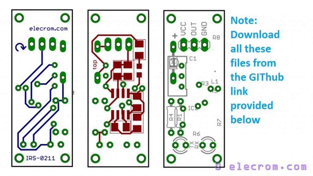
Infrared sensor module is very useful for making systems for obstacle detection, infrared proximity sensor, object detection or occupancy sensing applications . In this blog post a simple DIY infrared sensor module schematics and board layouts are presented. This IR sensor circuit is designed such as way that it can work on 3.3 V to 5.5 V supply voltage. Therefore this Infrared sensor circuit is Arduino, and Raspberry Pi compatible.
This IR sensor module is conceptualized as a small form factor board which can be fixed on any hardware or a mechanical structure. This compact IR sensor module is especially useful for autonomous robotics, line follower robots, DIY door openers, burglar alarms, and DIY object counters. The total BOM cost of this Infrared sensor module would be around $1 – $2, or Rs. 60 – Rs. 120 (excluding PCB manufacturing charges).
If you do not want to make a PCB, you can build this module on a general purpose matrix PCB as well.
How infrared sensor works?
To understand how this nifty little IR sensor works, please refer to the operating Principle section on this page – How to make IR sensor modules.
IR Sensor Module Schematic
Description
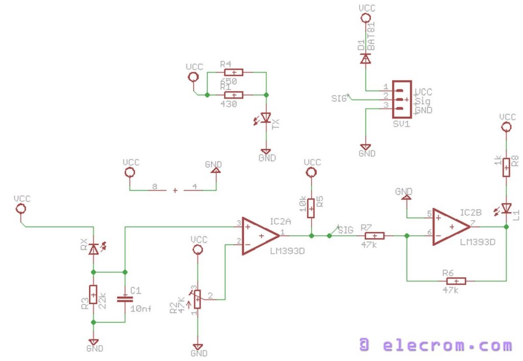
TX is the transmitting Infrared LED. It transmits fairly strong beam of the Infrared light. Resistors R4 and R1 control the intensity. Depending upon your requirement you can either use only R1 (stronger IR emitted), R4 (slightly lesser IR emitted) or both (even stronger IR). You can change the recommended values of R1 and R4 if you want to.
RX is the Infrared receiver diode. It is reverse biased with the VCC supply with a biasing resistor R3. Reverse leakage current flowing through the RX and R3, creates a voltage drop across R3. This voltage created across R3 is the sensing voltage. Stronger the incident IR radiation, more the leakage current and hence more voltage drop across R3. Capacitor C1 acts as a Low Pass Filter (LPF) to smooth out the sense voltage.
Potentiometer R2 provides the variable voltage to be used as a reference to compare the level of sense voltage. You can vary the potentiometer to increase or decrease this reference voltage thereby changing the sensitivity of the IR sensor’s output. The Infrared sensor’s output is labelled as SIG net.
Chip LM393 is the low power low offset voltage dual comparator. The First stage comparator (IC2A) acts as a non-inverting comparator. This compares the reference voltage with the sensing voltage. If sensing voltage goes above the reference voltage, output of the comparator (SIG) goes to VCC (logic high), else it goes to GND (logic low).
The second stage comparator (IC2B) is configured as an inverting buffer and its output is connected to the indicator LED (L1). This indicator LED gives the visual indication of the output signal. The LED glows when the output signal (SIG) is HIGH.
How to use?
- Connect VCC terminal on SV1 header to +5V (for 5V boards or controllers, such as Atmel AVR (Arduino Uno)), or to +3.3V (for 3.3V based boards or controllers, such as Atmel SAM (Arduino Due))
- Connect GND to the circuit Ground
- IR sensor output is available on the Sig terminal. This signal goes HIGH, when object is in the proximity of IR sensor, otherwise output stays low. Connect this terminal to the digital input pin on any suitable GPIO port of your microcontroller.
BOM
| # | Part | Value | Device | Package | Description |
| 1 | C1 | 10nf | C-EUC1206 | C1206 | CAPACITOR, European symbol |
| 2 | D1 | BAT81 | BAT81 | DO34-7 | DIODE |
| 3 | IC2 | LM393D | LM393D | SO08 | COMPARATOR |
| 4 | L1 | LEDCHIPLED_0805 | CHIPLED_0805 | LED | |
| 5 | R1 | 430 | R-EU_0204/7 | 0204/7 | RESISTOR, European symbol |
| 6 | R2 | 47K | R-TRIMM64W | RTRIM64W | Trimm resistor |
| 7 | R3 | 22k | R-EU_M1206 | M1206 | RESISTOR, European symbol |
| 8 | R4 | 650 | R-EU_0204/7 | 0204/7 | RESISTOR, European symbol |
| 9 | R5 | 10k | R-EU_M1206 | M1206 | RESISTOR, European symbol |
| 10 | R6 | 47k | R-EU_M1206 | M1206 | RESISTOR, European symbol |
| 11 | R7 | 47k | R-EU_M1206 | M1206 | RESISTOR, European symbol |
| 12 | R8 | 1k | R-EU_M1206 | M1206 | RESISTOR, European symbol |
| 13 | RX | IR sensor LED | LED3MM | LED3MM | LED |
| 14 | SV1 | MA03-1 | MA03-1 | PIN HEADER | |
| 15 | TX | IR transmitter LED | LED3MM | LED3MM | LED |

Downloads
You can download the eagle schematic, PCB layout files of this Infrared sensor module from the following GIT hub repository:
https://github.com/elecrom/elcrm_infrared_sensor
You can download all files in a single Zip file from here:
https://github.com/elecrom/elcrm_infrared_sensor/archive/master.zip
Ready made modules
Making things by our own hands is always fun!! However, if you are in a hurry, here are some readily available Infrared sensor Modules:
Low cost Infrared sensors (from Amazon):
 |
 |
 |
Low cost infrared sensors (from DX):
(Approx cost ~ $4 to $10 / INR 300 to 600, free shipping for many countries)
 |
 |
 |
#ir-sensor-module #modules #DIY


#
This blog post was amazing it provided us information about a simple DIY infrared sensor module schematics and board layouts are presented. Infrared sensor module is very useful for making systems for obstacle detection. Thanks for sharing. How accurate are your devices will give clear readings and that’s why one should always check the platforms that supply the best electronic input/ output devices, on which you can rely for accurate results.